Proximity tool
The Proximity tool connects objects based on their geometric proximity, in other words, how close they are to each other. You can connect objects within the same BIM model, however, the true power of the Proximity tool comes from connecting objects from different BIM models from different disciplines.
The big idea is that once the connection has been created it can be used for example in the Calculate Properties for Connected Objects tool to derive and copy data from one object to another. This enables you to enrich the model data in a new way. We call this message passing. There are many interesting use cases for this functionality. See the Examples below.
If you are familiar with Graph Theory, then you can think of the building elements as nodes (or vertices) of the graph, and the connections as the edges of the graph.
Note that the Proximity tool is currently in the beta phase. Please give it a try and send us feedback. We tried to take as many as possible use cases into account, but this is such a powerful concept, that I’m sure you will find new ways to use and configure the tool. Note that in the beta version, only the objects with 3D geometry are supported. Support for the 2D objects will come later. Also the configuration parameters might still change in the final version. There can still be limitations or bugs in the tool. If you find them, please let us know!
Creating Different Kinds of Graphs
The proximity tool creates undirected graph information to the model. The edges are unweighted.
Using the settings you can create three different kind of graph information:
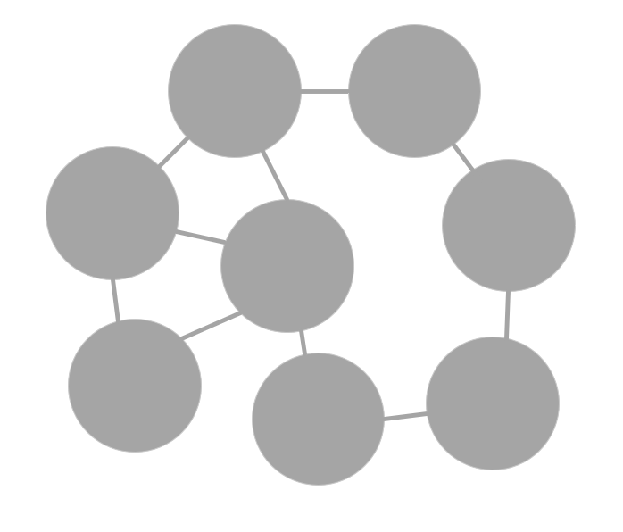
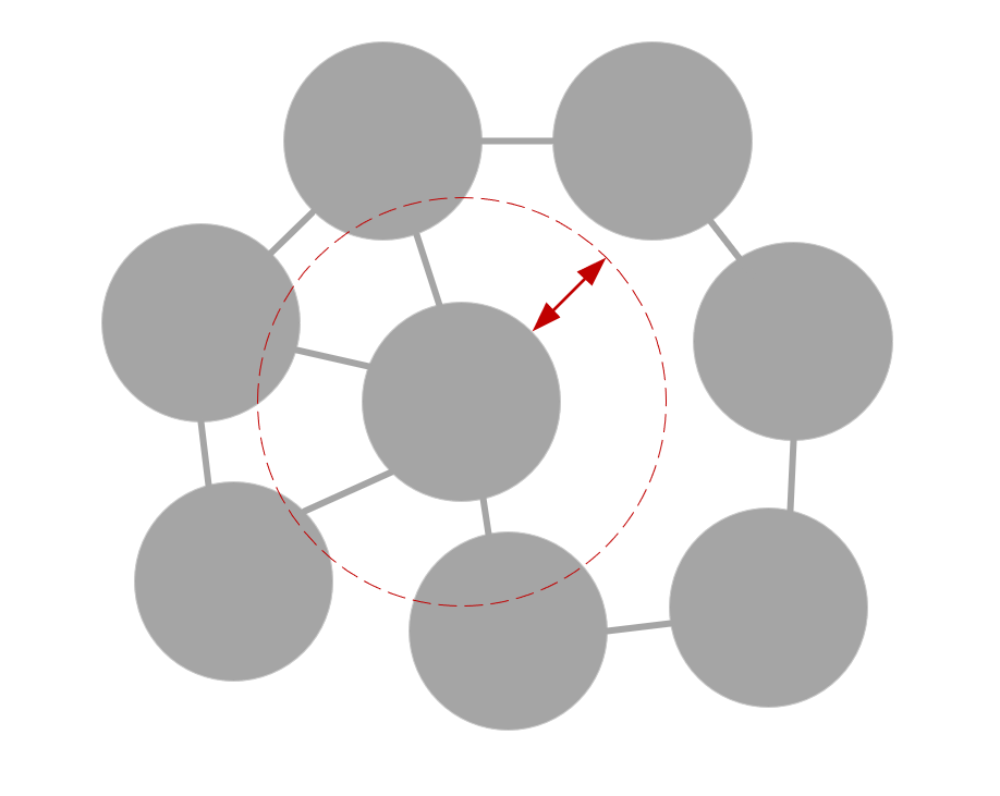
Basic graph
The connections are created between any building elements. Give the same group both to the Target Objects 1 and Target Objects 2. Use the Neighbours options for Connect setting.
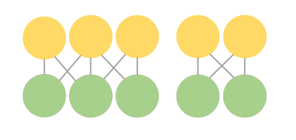
Bigraph
The connection is only created between building elements from different groups, not between building elements within the same group. Give the tool two distinct groups. Target Objects 1 and Target Objects 2 should not contain the same building elements. Use the Neighbours options for Connect setting.
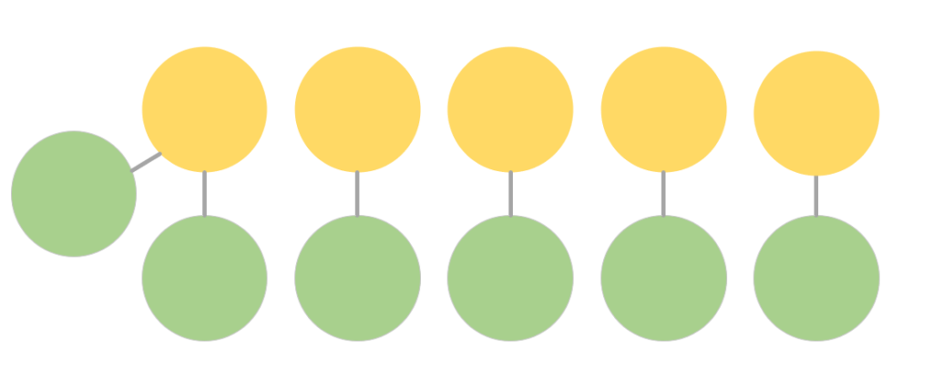
Bigraph for Nearest Distinct Neighbours
The connection is created only between building elements from the different groups. The additional restriction is that building elements from Target Objects 2 can only be connected to one building element from Target Objects 1, the closest neighbour. Give the tool two distinct groups. Target Objects 1 and Target Objects 2 should not contain same objects. Use the Nearest Distinct Neighbour option for Connect setting.
Settings
The Proximity tool finds neighbours for building elements. The neighbours mean building elements that are within a given maximum distance from the building element. The distance means the shortest distance between the surfaces of the building elements’ geometries.
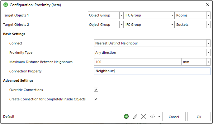
Target Objects 1
The first set of building elements to which the tool tries to find neighbours. Note that the building elements can be either single objects or even assemblies.
Target Objects 2
The second set of building elements to which the tool tries to find neighbours. Note that the building elements can be either single objects or even assemblies. Target Objects 2 has a special meaning when using the Nearest Distinct Neigbour option. See more details from the Creating Different Kinds of Graphs section above.
Connect
In different use cases, you want to find the proximity objects in different ways.
Neighbours. Use this option when you want to connect all the building elements within the Maximum Distance between Neighbours.
Nearest Distinct Neighbour. Use this option when you want to connect building elements from the Target Objects 2 only to the closest building element from the Target Objects 1.
Proximity Type
There are use cases where you want to limit the proximity search in different ways. For example, you might want to connect only the building elements (from Target Objects 2) that are above the building element (from Target Objects 1).
Any Direction. Use this option to find the building elements (from Target Objects 2) in any direction from the Target Objects 1 building element.
Above. Use this option to find building elements (from Target Objects 2) directly above the Target Objects 1 building elements. If the Target Objects 2 building element is within the Maximum Distance, but on the side or below the Target Objects 1 building element, then it is not connected to the Target Objects 1 building element.
Below. Use this option to find building elements (from Target Objects 2) directly below the Target Objects 1 building elements. If the Target Objects 2 building element is within the Maximum Distance, but on the side or above the Target Objects 1 building element, then it is not connected to the Target Objects 1 building element.
On the Side. Use this option to find building elements (from Target Objects 2) on the side of the Target Objects 1 building elements, in other words not directly above or below. If the Target Objects 2 building element is within the Maximum Distance, but directly above or below the Target Objects 1 building element, then it is not connected to the Target Objects 1 building element.
On the Side at the Same Level. Use this option to find building elements on the side of the Target Objects 1 building elements, in other words not directly above or below. The additional constraint is that the Target Objects 2 building element has to be at the same level as the Target Objects 1 building element. If the Target Objects 2 building element is within the Maximum Distance, but directly above or below, or on the side but higher or lower than the Target Objects 1 building element, then it is not connected to the Source 1 building element.
Maximum Distance between Neighbours
Use this option to define the maximum allowed distance between the neighbours. The building elements that are farther apart than the Maximum Distance are not connected. In other words the Maximum Distance between Neighbours define the neighbourhood of the building element.
Connection Property
Use this option to define the Connection Property name. Make sure you use unique names, if you want to run the tool multiple times on the same model (and don’t want to update or override the existing connections). The Connection Property can be used for example in the Calculate Properties for Connected Objects tool.
Override Connections
Use this option to choose whether you want to override (checked) or update (unchecked) the Connection Property, if it already exists in the model. There are use cases for both. Maybe you want to run the tool multiple times for the same Target Objects 1 building elements but for different sets of Target Objects 2 building elements using different logic or Maximum Distance. Then you want to update/add to the Connection Property. On the other hand, if you make a mistake, you can override the Connection Property with a rerun.
Create Connection for Completely Inside Objects
The tool calculates the distance between the closest surfaces of the objects. However, sometimes the Target Objects 2 building elements can be completely inside the Target Objects 1 building element and ‘deeper’ than the Maximum Distance between Neighbours. If you want to connect these objects, turn this option on.
Automation
Proximity tool is almost always used together with another tool, like the Calculate Properties for Connected Objects tool. Remember that you can easily automate running both tool with a template or scripts. Simply configure your tools in the Simplebim UI, then copy the configurations to your template.
Examples
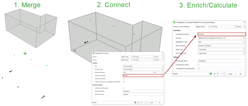
Find the number and type of electrical sockets for each room
Let’s say you want to make a bill of quantities for sockets based on the rooms they belong to. The room objects (spaces) are in the architectural model. The electrical sockets have been modeled by the electrical engineer to the electrical model. These two models and their objects don’t know anything about each other. So, what do you do? Proximity tool to the rescue! Merge the architectural model and the electrical model. Create a group for all the space objects (or rooms), and another group for all the sockets. Run the proximity tool. It will create a connection between the rooms and the sockets within each room. You can now use this connection to calculate the number of sockets to your space objects. Or copy the type information from the sockets to the rooms. Or copy the room name and number from the space objects to the sockets. You can export the data back to IFC and use it in some of your downstream applications. Or create an Excel export including the enriched and derived data. Problem solved. Pretty cool!
Find doors for walls
Let’s say the internal walls in your model know their fire rating, but the doors don’t. Or you are not sure, if these two pieces of data are inline. You cannot have a lower-rated door in a higher-rated wall. That would not make sense. Even though the building elements are probably in the same model, they don’t always have a ready-made connection between them. Or even if they do, this might be hard to use for automated data enrichment or checking. So, what do you do? Proximity tool to the rescue! Create a group for all the internal walls and another group for all the doors. Run the proximity tool, which will create a connection between the walls and the doors within their proximity. Now you can use this connection to copy the fire rating data from the wall to the door. Or the other way around. Afterward, you have the fire rating data in all the relevant building elements. Or if both the walls and doors already had the fire rating data you can now cross-check, and mark the building elements with the different fire rating value as their counterpart. Problem solved. Pretty cool.
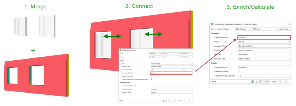
Find windows for precast elements
What if the precast wall factory wants to know what kind of windows there are in specific precast wall elements? Depending on the window type, they might for example need to create different kinds of attachments to the precast element. The windows are in the architectural model. The precast walls have been modeled by the structural engineer to the structural model. The objects and the data are in different BIM models. They don’t know anything about themselves. So, what do you do? Proximity tool to the rescue! Merge the architectural model (or its windows) and the structural model. Create a group for all the windows. Create another group for the precast wall assemblies. Now run the Proximity tool to connect the precast walls to the windows that are within their proximity. Finally, use this connection to copy the window type information to the precast elements. Export the model back to IFC or create a dataset out of the derived and enriched data. Problem solved. Pretty cool.
Find spaces, that are served by an HVAC system
One interesting idea is to use the proximity tool for marking the rooms that are served by a specific HVAC system. Again the rooms (spaces) and the HVAC systems and their object are created into different models. They don’t know anything about each other. So, what do you do? Proximity tool to the rescue! Merge the architectural and HVAC models. Create a group of objects for the HVAC systems and another group for all the spaces. Run the Proximity tool to connect the rooms and HVAC objects. Use this connection in the Calculate Properties for Connected Objects to either mark the rooms as served, or even copy the system name from the HVAC objects to some property of the room. Problem solved. Pretty cool.
Match colors of sprinklers and ceilings
This use case I could not have come up by myself. In a high-end building the ceilings and the sprinkler heads need to have the same color. The ceilings are modeled by the architect to the architectural model and the sprinkler heads by the sprinkler designer to the sprinkler model. The data and the objects are in different models, so they don’t know anything about themselves, let alone their colors. So, what do you do? Proximity tool to the rescue! Merge the architectural and the sprinkler model. Create a group for all the ceilings and another group for all the sprinkler heads. Now run the Proximity tool to connect each sprinkler head to the closest ceiling. Finally, use this connection to copy the color information from the ceiling to the sprinkler head. Export the data back to IFC, or create an Excel table from the data and you are done. Problem solved. Pretty cool.
Calculate the area of windows and doors for rooms
What are the window and door areas in a room? This seems like a trivial question, but many times this information is not in the model. The rooms, windows, and doors might be in the same architectural model, but they still might not know anything about each other. So, what do you do? Proximity tool to the rescue! Create a group for all the rooms and another group for all the doors and windows. Now run the Proximity tool to connect the rooms to the relevant windows and doors. Use this connection to summarize the areas from the windows and doors and assign the end result to a property of the room object. Export the data back to IFC, or create an Excel table from the data and you are done. Problem solved. Pretty cool.
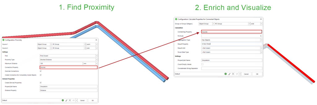
Check that the hot and cold water pipes are not too close to each other
One of the more traditional uses of proximity tool is to find for example if the hot and cold water pipes have required distance from each other. Yes, the proximity tool can also be used for this kind of more traditional clash detection task. Even though the objects in this case are in the same model, they don’t know the distances between them. Model author tools don’t create this information for you. So what do you do? Proximity tool to the rescue! Create a group for all the cold water pipes and another group for all the hot water pipes. Run the Proximity tool with the maximum distance that is the minimum distance the hot and cold pipes should have. The Proximity tool will create a connection between pipes that are too close to each other. You can now use this connection to mark the ‘too close’ pipes from the model. Highlight or colorize the problematic pipes from the model, or create BCF issues out of them. Problem solved. Pretty cool.